STM32 Development Board with WIFI Module 51 Single Chip ARM |
Описание товара
Description:
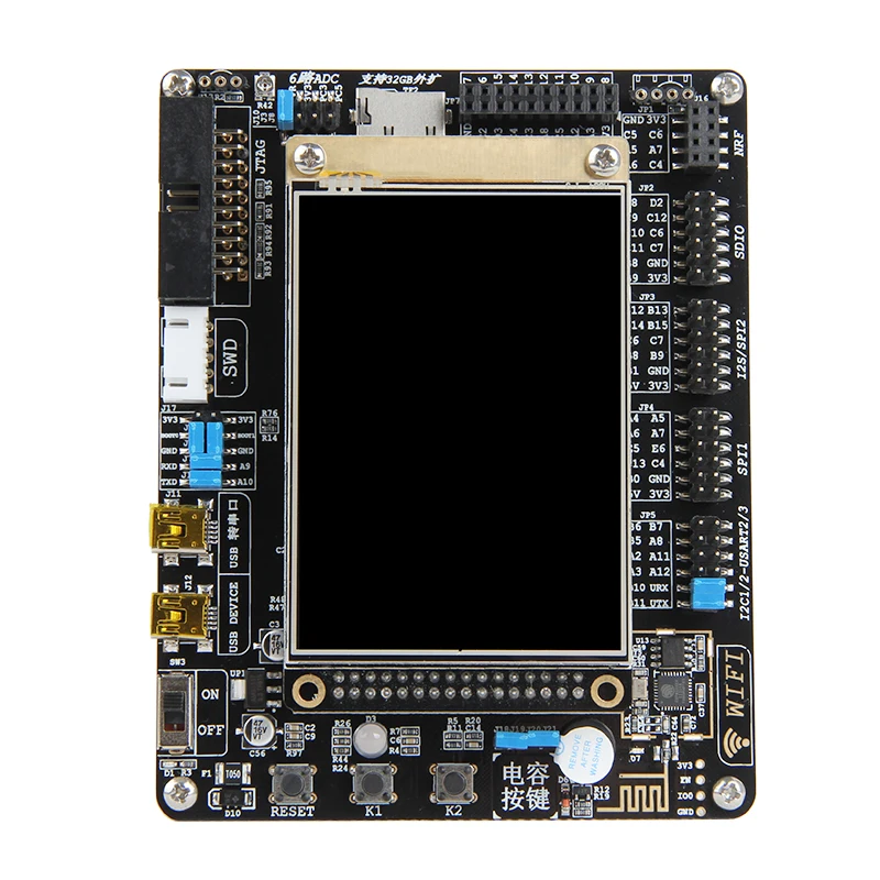
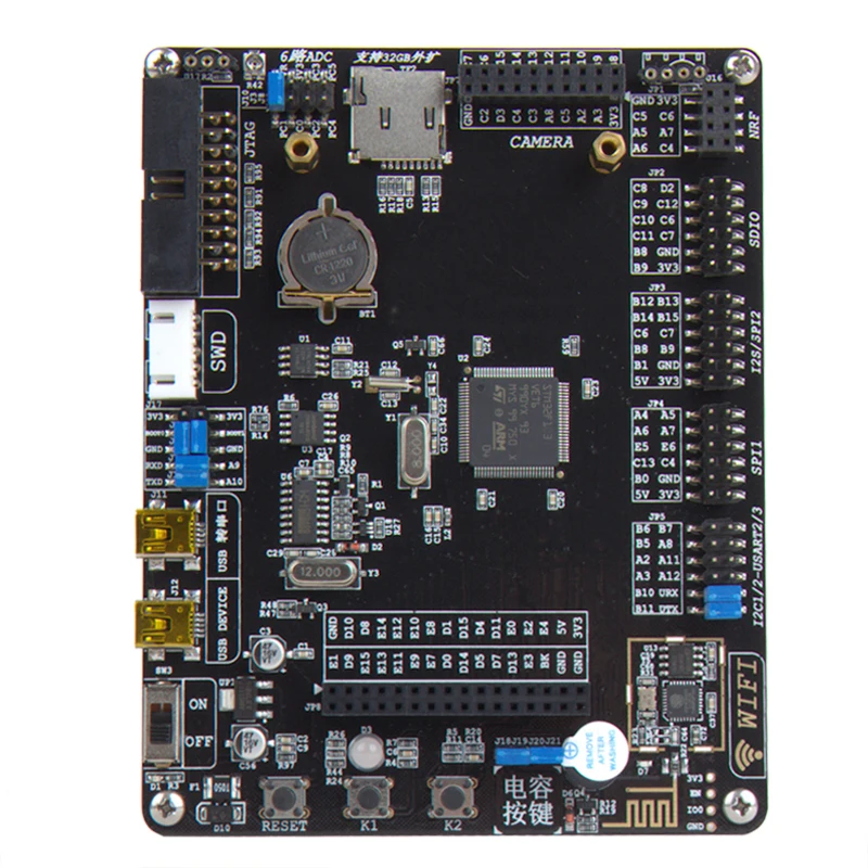
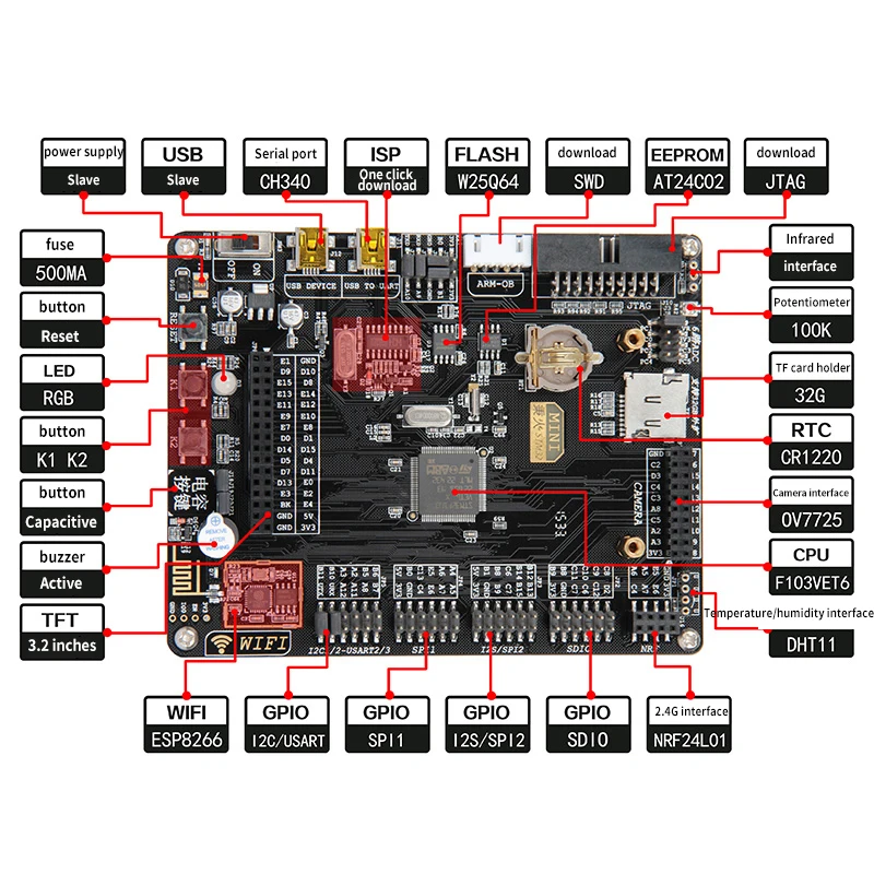
Description:Features:Black oil PCB immersion gold process, high qualityOnboard serial port type Wifi ESP8266The standard usart, iic, spi, and sdio communication interfaces are used in the form of pin headers, which are used for communication between external modules and boards.Development board hardware configuration detail table (please check carefully):Size: 13*10CMPCB: 2 layers, black immersion goldCPU: STM32f103Vet6, 100pIN, 512K FLASH, 64KRAMWIFI: Onboard WIFI model: ESP8266, UART interfaceBluetooth: External HC05 Bluetooth moduleWireless: External 2.4G wireless NRF24L01 moduleFLASH: Model: W25Q64, capacity 8MBYTEEEPROM: Model: AT24C02, capacity 256 bytesSD card: TF card (including 32GB) can be expanded beyond 32GBRTC: 1 CR1220 battery holderPower input: USB5V inputPower output: LDO: AMS1117-3.3, can output 3.3V and 5VFuse; 1 500MA self-recovery fuseBuzzer: 1 active buzzerPotentiometer: 1 100K precision chip potentiometerButton: 1 reset, 2 normal buttons, 1 capacitor buttonLED: 1 RGB LED, 1 power supply Led, 1 wif communication LEDLCD: can be connected to a 3.2-inch resistive screen or a 5-inch capacitive screenSerial port: 1 way USB to serial port (CH340)USB: 1 USB-devicef interface for USB communicationDownload: 1: There are 2 download interfaces, 1 SWD interface, 1 JTAG interface 2: Supports DAP / JLINK / ULINK 2 / st-link / arm-oB and other emulators 3: Support serial port SP one-click downloadCamera: Can expand 30W color 0V7725 camera moduleTemperature and humidity: External temperature and humidity sensor DHT11 moduleInfrared: external HS0038 infrared receiverGPIO: SDIO, SPI 1 / 2, 12C1/2, USART 1 / 2 / 3Hardware configuration (high configuration with wifi):Hardware size:
1. Network communication data (WFi and Ethernet routines)1: Onboard WIF, mobile APP control development board, open the intelligent eraWiFi performance profile:1, ESP8266 is a serial port type WIFI, the speed is relatively low, can not be used to transmit large amounts of data such as images or video.It is mainly used in applications where data transmission is relatively small, such as temperature and humidity information, and the switching amount of some sensors.2. In the experiment of WIFI transparent transmission, our measured data is: in the LAN, WIFI works in STA mode.The MCU sends data to the host computer through ESP8266, sending 1120 bytes each time, the time interval is 100ms, very stable, and the standby time is 24 hours.3. Application areas: Internet of Things, intelligent community, modern agriculture, modern medical2: APP profile, only supports Android does not support 10S2-1: Distribution networkBurn the supporting program, after the WIFI signal is successfully configured, search the ESP8266 on the mobile phone.The WIFI signal is emitted. The signal name is: BinghuoLink, which can be connected without a password.Set the password yourself in the program). Run the installed mobile phone app, and use it on the APP.The IP and port have been initialized, just click on the connection, after the connection is successful, there will beShow, then you can implement the control development board (APP source is about to open source, perfect)2-2: InterfaceAPP has two interfaces, the front is the interface that controls the development board hardware, and the second is WiFI.Transparent transmission interface, that is, the APP sends information to the development board, and then the development board sends the information back to the APP.EMWIN renderings, detailed screenshots of supporting routines:1. The integrated routine requires a bare board + 3.2 inch LCD screen (or 5 inch capacitive screen) to work together.Use, single bare board can not achieve this experiment (screen needs to be purchased separately)2, the following screenshots are 3.2-inch screen effect, resolution 320 * 240.5-inch screen resolution is 800 * 480 (5-inch renderings again do not demonstrate)3, the following pictures are obtained by the screenshot function, that is, the LCD screenshot routine (BMP format)1. Comprehensive routine interface, a total of 10 sub-applications (you can add applications yourself)After entering the main page, the development board is normal. Available fromTry to open each app and try to use it. There are someAPP requires an external hardware module for normal use2, KEY breathing lamp application1: Run the KEY APP to control the LEDs using the buttons on the board.After entering the APP interface, press the KEY1 button on the development board to control the LED to turn off.You can also click on the two "KEY" buttons on the interface. When the button is pressed, it willA corresponding LED light is illuminated. Pull the slider toControl the LED light to run as a running light for a short period of timeThe position of the slider is related to how fast the LED light flashes.2: Click the "Touch Calibration" button on the interface, it will enter the touch correction interface, enter the interface and click the screen.Then follow the prompts and click on the small circle that appears on the interface. After the calibration is successful, it will return to the main interface.3, Breathing breathing light applicationRun the Breathing APP to enter the RGB lights on the board.Line coloring. The three parameters on the APP interface representR, G, B values of the RGB888 color format, by slidingThe bar can set the parameter value, the circle below the interface will be the threeThe color of the parameter synthesis shows that the RGB lights on the boardIt will also change the color.4, ADC Converte applicationThe ADC APP can collect the voltage and display the voltage as a waveform. Rotate the potentiometer on the upper right side of the board.Changing the input voltage also changes the voltage detected on the APP.5, EEPROM application1. EEPROM APPI can be on the EEPROM on the boardRead and write data, when you open the app, it will automaticallyWrite to the 0-255 address of the EEPROM in turnAutomated testing of data with the same addressThe test results are displayed at the bottom of the screen.2: Users can write custom to specific addressesThe data. After clicking the input box, the button will pop up.Disk, you can use the keyboard to enter numbers6, Clock real time clockThe Clock APP uses the RTC function of the STM32.If you connect the battery holder on the development board to the battery, the development boardRTC will continue to run after disconnecting the main power, next timeWhen you open the Clock APP, you will see the update time.(The battery holder is below the LCD screen and the battery model is the battery.The model number is: CR1220. The development board does not have a matching battery by default. )7, USB analog U diskUSB APP is an analog U disk program that canThe FLASH on the board is simulated into a USB flash drive, on the computerView the files on FLASH in the form of a USB flash drive8, WiFi application1. Use WIFI APP to perform WIFI communication and demonstrationTransfer text data to and from the server using the TCP protocol2. This experiment requires wireless routing support, and the computer andSTM32 should be connected to the same router, routerThe gateway address is 192.168.1.1. If the address does not match,Need to modify the program9, Humidure temperature and humidity applicationHumiture app can be used to display detectedTemperature and humidity data. Needed before powering upTo connect the DS18B20 to the upper right corner of the boardTemperature sensor or DHT11 temperature and humidity sensorIf the connection is normal, you can open the app directly.See data for DS18B20 or DHT11(DS18B20 or DHT11 modules need to be purchased separately)10, Camera applicationCamera APP is used to develop the board expansion camera function. Just above the development board isCamera interface, can expand our fire eye 0V7725 camera. Normal LCD screenThe data captured by the camera is displayed in real time for real-time monitoring.(This rendering shows the 0V7725 camera, you need to buy it separately, click to view11, Calculator applicationCaculator is a calculator program with normalThe calculator is no different. Nothing to note, feel free use12, User applicationThese two User are user-defined functions and areNo function application added, here we reserve to add to the userAdd the features you need (refer to other application programming implementations)13, Phone applicationPHONE is a phone dialing application. The application needsUse GSM module together, and GSM module needsTo access the SM card, the wiring method is shown below.(GSM module needs to be purchased separately)14, Message application1, Message is to send SMS application,It also needs to be used in conjunction with the GSM module.2, in the application interface you can view the draft boxIn the text message, you can also click "new..."Create a new text message in a column, in the SMS editing communityYou can write and send a text message.
Понравился дизайн свитера, решила заказать, товар пришел быстро, цвет и размер подошёл. Все как на фото. Доставка не дала долго... Читать отзыв полностью...
Давно искала такие стульчики. Долго присматривалась. Взяла четыре и не пожалела. Очень удобно: когда надо ставишь за стол, если не... Читать отзыв полностью...
Заказывала эти симпатичные блокнотики на подарки. Удобно и по делу. Посылка пришла вовремя, блокноты не помяты, целые и невредимые, липкая... Читать отзыв полностью...
Решила заказать на пробу данный товар, пришел быстро. Качество материала очень хорошее, стирается легко. А главное подошёл к моему столу... Читать отзыв полностью...


Понравился дизайн свитера, решила заказать, товар пришел быстро, цвет и размер подошёл. Все как на фото. Доставка не дала долго... Читать отзыв полностью...